1
SIGNALS
AND
SYSTEMS
1.0
INTRODUCTION
As described in the Foreword, the intuitive notions
of
signals and systems arise in a rich va-
riety
of
contexts. Moreover, as we will see in this book, there is an analytical
framework-
that is, a language for describing signals and systems and an extremely powerful set
of
tools
for analyzing
them-that
applies equally well
to
problems
in
many fields. In this chapter,
we begin our development of the analytical framework for signals and systems by intro-
ducing their mathematical description and representations. In the chapters that follow, we
build on this foundation in order
to
develop and describe additional concepts and methods
that add considerably both
to
our understanding
of
signals and systems and
to
our ability
to
analyze and solve problems involving signals and systems that arise in a broad array
of
applications.
1.
1
CONTINUOUS-TIME
AND
DISCRETE-TIME SIGNALS
1 . 1 . 1 Examples
and
Mathematical
Representation
Signals may describe a wide variety
of
physical phenomena. Although signals can be rep-
resented in many ways, in all cases the information in a signal is contained in a pattern
of
variations
of
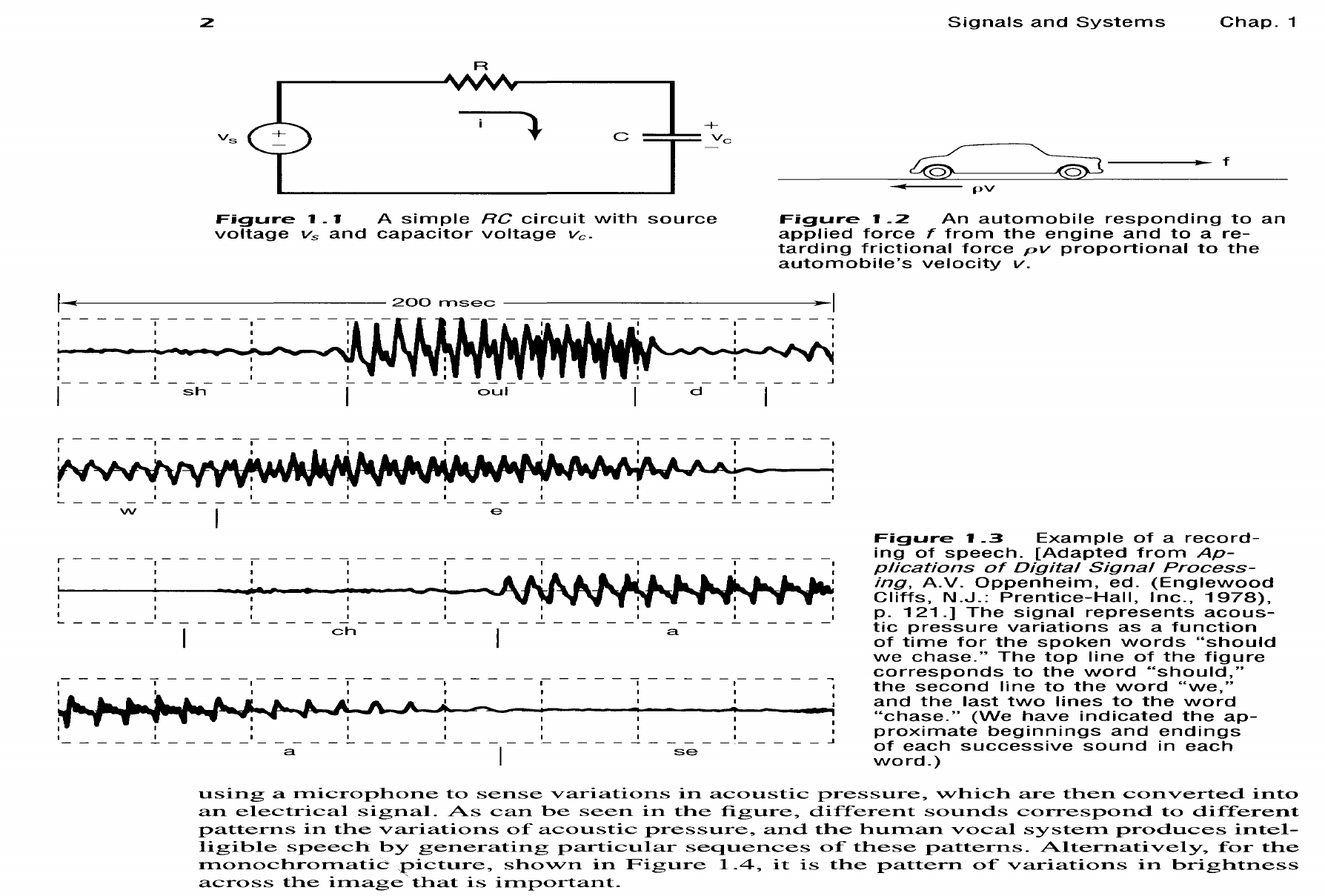
some form. For example, consider the simple circuit in Figure 1.1. In this case,
the patterns
of
variation over time in the source and capacitor voltages,
v,
and
Vc,
are exam-
ples
of
signals. Similarly, as depicted in Figure 1.2, the variations over time
of
the applied
force
f and the resulting automobile velocity v are signals. As another example, consider
the human vocal mechanism, which produces speech by creating fluctuations in acous-
tic pressure. Figure
1.3
is
an illustration
of
a recording
of
such a speech signal, obtained by
1
2
Signals
and
Systems
Chap.
1
R
c
~pv
Figure 1. 1 A
simple
RC
circuit
with
source
voltage
Vs
and
capacitor
voltage
Vc.
Figure 1
.2
An
automobile
responding
to
an
applied
force
t
from
the
engine
and
to
a
re-
tarding
frictional
force
pv
proportional
to
the
automobile's
velocity
v.
~-------------------200msec--------------------~
I I I I
1
_____
.!_
_____
1
_____
!._
_____
1
__________
~
_____
I
_____
J
j
sh
oul d
r - - - -
-~-
- - - - I - - - - I - - - - -
~-
- - - - I - - - -
-~-
- - - - I - - - - -~
I
I
I I I I I I I
~-------------------------------------------
w
e
r - - - -
-~-
- - - - I - - - - I - - - - -
~-
- - - - I - - - -
-~-
- - - - I - - - -
-~
I I I
I
~
_____
1
_____
~
____
~
_____
1
_____
.!_
_____
I
_____
~
_____
I
ch a
I I I I
1
_____
~
_____
1
_____
~
_____
1
_____
I
_____
~
_____
1
_____
J
a
I
se
Figure
1.3
Example
of
a
record-
ing
of
speech.
[Adapted
from
Ap-
plications
of
Digital
Signal
Process-
ing,
A.V.
Oppenheim,
ed.
(Englewood
Cliffs,
N.J.:
Prentice-Hall,
Inc.,
1978),
p.
121.]
The
signal
represents
acous-
tic
pressure
variations
as
a
function
of
time
for
the
spoken
words
"should
we
chase."
The
top
line
of
the
figure
corresponds
to
the
word
"should,"
the
second
line
to
the
word
"we,"
and
the
last
two
lines
to
the
word
"chase."
(We
have
indicated
the
ap-
proximate
beginnings
and
endings
of
each
successive
sound
in
each
word.)
using a microphone
to
sense variations in acoustic pressure, which are then converted into
an electrical signal. As can be seen in the figure, different sounds correspond
to
different
patterns in the variations of acoustic pressure, and the human vocal system produces intel-
ligible speech by generating particular sequences of these patterns. Alternatively, for the
monochromatic picture, shown in Figure 1.4, it is the pattern
of
variations in brightness
across the image, that is important.
